Victoria Foundation Repair: Epoxy Inject Cracks

Concrete Crack Repair – Epoxy Injection Concrete Crack Repair – Epoxy Injection
By Aaron Kuertz

Concrete foundations can develop cracks over time. These cracks can then let in water and damage the interior contents of the basement. In severe cases, cracks in a concrete basement wall can signify that there is a structural defect with the wall. Whether it is to stop water or to structurally reinforce the concrete crack, epoxies can be injected into it.

Causes of Concrete Cracks

The most common is that the concrete actually shrinks as it cures. This curing process reduces the amount of water in the concrete and it shrinks in volume. This shrinkage causes stresses to occur and to relieve this stress, the concrete cracks. This is a normal process and it is not to be a cause of concern. However, they can still let in water and damage the interior contents of a basement. Shrinkage cracks usually are less than 1/16″ in width and remain a constant width throughout the life of a foundation.

A more serious concern is when the concrete has been structurally damaged. This could be occurring for a number of reasons. One of which is that the house is settling into the ground. Or the house may be sliding down a hillside. A very common reason, especially in older homes is the lateral force exerted by the soil onto the foundation. This will be evident by a bowing in of the concrete wall.

How to Determine if a Crack is Structural

There are a few easy ways to determine if a concrete crack is the result of a structural compromise in the foundation.

  1. The crack runs on a severe diagonal
  2. Horizontal cracks in a foundation wall indicate a serious problem
  3. Crack widths that increase over time.
  4. Cracks with widths in excess of 3/4″

If you are not sure or are concerned, you should contact a professional to determine if the crack is structural in nature and how to fix it.

Epoxy Injection

Whether it is a shrinkage crack or a structural crack, epoxies can be injected to make the repair. Epoxy injection is done from the interior of the basement, so no excavation on the outside needs to be done. The epoxies hardened in the crack and reinforce the concrete. They will fill the crack entirely from the bottom to the top and from front to back. In many cases, the epoxies are stronger than the concrete itself. The concrete crack will no longer be able to allow water to enter the basement.

This article is written by Aaron Kuertz with Applied Technologies. Aaron has been in the waterproofing industry since 1998. Applied Technologies is a manufacturer and supplier to professional waterproofing contractors and homeowners in the United States. To learn more about epoxy concrete crack repair visit Applied Technologies on the web.

Article Source: http://EzineArticles.com/?expert=Aaron_Kuertz
http://EzineArticles.com/?Concrete-Crack-Repair—Epoxy-Injection&id=2463767
[mappress]

Victoria -Foundation Repair

Foundation Repair

By Ken Marlborough

The principal function of a foundation of a home is to transfer the weight of a structure to its underlying soil and rocks. One of the factors that bring about the need for foundation repairs is improper foundation settling. Foundation settlement can devalue structures and also render them unsafe. Building on expansive clay, compressive or improperly contracted fill soils and improper maintenance in and around foundations are some of the major reasons of improper foundation settling. Another reason for improper foundation settlement is undetected or unsuspected air pockets in the ground below the area of construction. These may cave in and cause the integrity of the foundation to be compromised.

General symptoms of a structure needing foundation repairs are bulging or cracked walls and doors that don’t close properly. Building on expansive soils is the main culprit for foundation settlement. When only one part of the foundation either settles or heaves, cracks are formed in the foundation. The exterior warning signs of improper floor settling are rotation of walls, displaced moldings, cracked bricks and foundation and separation around doors and windows from the walls. Interior warning signs of improper floor settling are cracks on the floor, sheet rock and misalignment in doors and windows.

There are many ways of doing foundation repair. Cement, stone, steel or wood were used extensively in past techniques. They would be forced into the ground in a bid to salvage the strength of these foundations. However, this type of repair work has been known to be futile. Two of the most successful ways of foundation repairs are slab jacking and the Piering method. Piering is also known as hydraulic jacking.

Slab jacking is the process of adding grout beneath a slab or beam. This produces a lifting force and restores the said beam or slab to almost its original elevation and adds to its strength. Care should be taken that the amount of sand should be perfect while adding grout.

During Piering, steel posts are driven through unstable soil. Hydraulic jacks are used to stabilize concrete slabs which are weakened due to the changes taking place in the underlying soil. Steel beams are used in the Piering method because concrete has great compressive strength. Though Piers are able to transfer huge downward loads without the help of reinforcing steel, steel is used in the piers for prevention of the pier from being pulled apart or sheared by forces of the expansive soils. The repairs normally take 21 to 30 days, however this time frame can vary depending on soil conditions and weather delays.

Foundation Repairs provides detailed information about foundation repair, do-it-yourself foundation repair, foundation leak repair, and more. Foundation Repairs is affiliated with Roof Shingles.

Article Source: http://EzineArticles.com/?expert=Ken_Marlborough
http://EzineArticles.com/?Foundation-Repair&id=119865

Del RiVictoria -Foundation Repair

Foundation Repair

By Ken Marlborough

The principal function of a foundation of a home is to transfer the weight of a structure to its underlying soil and rocks. One of the factors that bring about the need for foundation repairs is improper foundation settling. Foundation settlement can devalue structures and also render them unsafe. Building on expansive clay, compressive or improperly contracted fill soils and improper maintenance in and around foundations are some of the major reasons of improper foundation settling. Another reason for improper foundation settlement is undetected or unsuspected air pockets in the ground below the area of construction. These may cave in and cause the integrity of the foundation to be compromised.

General symptoms of a structure needing foundation repairs are bulging or cracked walls and doors that don’t close properly. Building on expansive soils is the main culprit for foundation settlement. When only one part of the foundation either settles or heaves, cracks are formed in the foundation. The exterior warning signs of improper floor settling are rotation of walls, displaced moldings, cracked bricks and foundation and separation around doors and windows from the walls. Interior warning signs of improper floor settling are cracks on the floor, sheet rock and misalignment in doors and windows.

There are many ways of doing foundation repair. Cement, stone, steel or wood were used extensively in past techniques. They would be forced into the ground in a bid to salvage the strength of these foundations. However, this type of repair work has been known to be futile. Two of the most successful ways of foundation repairs are slab jacking and the Piering method. Piering is also known as hydraulic jacking.

Slab jacking is the process of adding grout beneath a slab or beam. This produces a lifting force and restores the said beam or slab to almost its original elevation and adds to its strength. Care should be taken that the amount of sand should be perfect while adding grout.

During Piering, steel posts are driven through unstable soil. Hydraulic jacks are used to stabilize concrete slabs which are weakened due to the changes taking place in the underlying soil. Steel beams are used in the Piering method because concrete has great compressive strength. Though Piers are able to transfer huge downward loads without the help of reinforcing steel, steel is used in the piers for prevention of the pier from being pulled apart or sheared by forces of the expansive soils. The repairs normally take 21 to 30 days, however this time frame can vary depending on soil conditions and weather delays.

Foundation Repairs provides detailed information about foundation repair, do-it-yourself foundation repair, foundation leak repair, and more. Foundation Repairs is affiliated with Roof Shingles.

Article Source: http://EzineArticles.com/?expert=Ken_Marlborough
http://EzineArticles.com/?Foundation-Repair&id=119865

Structural Engineering 101 | Victoria

Structural engineering is a field of engineering dealing with the analysis and design of structures that support or resist loads economically. Structural engineering is usually considered a specialty within civil engineering, but it can also be studied in its own right.

Structural engineers are most commonly involved in the design of buildings and large nonbuilding structures but they can also be involved in the design of machinery, medical equipment, vehicles or any item where structural integrity affects the item’s function or safety. Structural engineers must ensure their designs satisfy given design criteria, predicated on safety (e.g. structures must not collapse without due warning) or serviceability and performance (e.g. building sway must not cause discomfort to the occupants).

Structural engineering theory is based upon physical laws and empirical knowledge of the structural performance of different geometries and materials. Structural engineering design utilises a relatively small number of basic structural elements to build up structural systems that can be very complex. Structural engineers are responsible for making creative and efficient use of funds, structural elements and materials to achieve these goals.

Contents

  • 1 Structural engineer
  • 2 History of structural engineering
  • 3 Structural failure
  • 4 Specializations
    • 4.1 Building structures
    • 4.2 Earthquake engineering structures
    • 4.3 Civil engineering structures
    • 4.4 Mechanical structures
  • 5 Structural elements
    • 5.1 Columns
    • 5.2 Beams
    • 5.3 Struts and ties
    • 5.4 Plates
    • 5.5 Shells
    • 5.6 Arches
    • 5.7 Catenaries
  • 6 Structural engineering theory
  • 7 Materials
  • 8 See also
  • 9 References
  • 10 External links

Structural engineer

Etymology
The term structural derives from the Latin word structus, which is “to pile, build, assemble”. The first use of the term structure was c.1440.[3] The term engineer derives from the old French term engin, meaning “skill, cleverness” and also ‘war machine’. This term in turn derives from the Latin word ingenium, which means “inborn qualities, talent”, and is constructed of in- “in” + gen-, the root of gignere, meaning “to beget, produce.” The term engineer is related to ingenious.[4]

The term structural engineer is generally applied to those who have completed a degree in civil engineering specializing in the design of structures, or a post-graduate degree in structural engineering. However, an individual can become a structural engineer through training and experience outside educational institutions as well, perhaps most notably under the Institution of Structural Engineers (UK) regulations. The training and experience requirements for structural engineers varies greatly, being governed in some way in most developed nations. In all cases the term is regulated to restrict usage to only those individuals having specialist knowledge of the requirements and design of safe, serviceable, and economical structures.

The term engineer in isolation varies widely in its use and application, and can, depending on the geographical location of its use, refer to many different technical and creative professions in its common usage.

Structural engineers are responsible for engineering design and analysis. Entry-level structural engineers may design the individual structural elements of a structure, for example the beams, columns, and floors of a building. More experienced engineers would be responsible for the structural design and integrity of an entire system, such as a building.

Structural engineers often specialise in particular fields, such as bridge engineering, building engineering, pipeline engineering, industrial structures or special structures such as vehicles or aircraft.

Structural engineering has existed since humans first started to construct their own structures. It became a more defined and formalised profession with the emergence of the architecture profession as distinct from the engineering profession during the industrial revolution in the late 19th Century. Until then, the architect and the structural engineer were often one and the same – the master builder. Only with the understanding of structural theories that emerged during the 19th and 20th century did the professional structural engineer come into existence.

The role of a structural engineer today involves a significant understanding of both static and dynamic loading, and the structures that are available to resist them. The complexity of modern structures often requires a great deal of creativity from the engineer in order to ensure the structures support and resist the loads they are subjected to. A structural engineer will typically have a four or five year undergraduate degree, followed by a minimum of three years of professional practice before being considered fully qualified.

Structural engineers are licensed or accredited by different learned societies and regulatory bodies around the world (for example, the Institution of Structural Engineers in the UK). Depending on the degree course they have studied and/or the jurisdiction they are seeking licensure in, they may be accredited (or licensed) as just structural engineers, or as civil engineers, or as both civil and structural engineers.

Structural Failure 101 | Victoria

Structural failure refers to loss of the load-carrying capacity of a component or member within a structure or of the structure itself. Structural failure is initiated when the material is stressed to its strength limit, thus causing fracture or excessive deformations. The ultimate failure strength of the material, component or system is its maximum load-bearing capacity. When this limit is reached, damage to the material has been done, and its load-bearing capacity is reduced permanently, significantly and quickly. In a well-designed system, a localized failure should not cause immediate or even progressive collapse of the entire structure. Ultimate failure strength is one of the limit states that must be accounted for in structural engineering and structural design.

Contents

  • 1 Dee bridge disaster
  • 2 First Tay Rail Bridge
  • 3 First Tacoma Narrows Bridge
  • 4 de Havilland Comet
  • 5 Ronan Point
  • 6 Hyatt Regency walkway
  • 7 Oklahoma City bombing
  • 8 9/11
  • 9 I-35W Bridge Collapse
  • 10 See also
  • 11 References
  • 12 External links

Dee bridge disaster

The Dee bridge after its collapse

On 24 May, 1847 the Dee Bridge collapsed as a train

passed over it, with the loss of 5 lives. It was designed by Robert Stephenson, using cast iron girders reinforced with wrought iron struts. The bridge collapse was the subject of one of the first formal inquiries into

a structural failure. The result of the inquiry was that the design of the structure was fundamentally flawed, as the wrought iron did not reinforce the cast iron at all, and due to repeated flexing it

suffered a brittle failure due to fatigue.[1]

First Tay Rail Bridge

The Dee bridge disaster was followed by a number of cast iron bridge collapses, including the collapse of the first Tay Rail

Bridge on 28 December 1879. Like the Dee bridge, the Tay collapsed when a train passed over it causing 75 people to lose their lives. The bridge failed because of poorly made cast iron,

and the failure of the designer Thomas Bouch to consider wind loading on the bridge. The collapse resulted in cast iron largely being

replaced by steel construction, and a complete redesign in 1890 of the Forth Railway Bridge. As a result, the Forth Bridge

was the first entirely steel bridge in the world.[2]

First Tacoma Narrows Bridge

Tacoma Narrows Bridge collapsing

The 1940 collapse of Tacoma Narrows Bridge, as the original Tacoma Narrows Bridge is known, is

sometimes characterized in physics textbooks as a classical example of resonance; although, this description is misleading. The catastrophic vibrations that destroyed the bridge were not due to

simple mechanical resonance, but to a more complicated oscillation between the bridge and winds passing through it, known as aeroelastic flutter. Robert H. Scanlan, father of the field of bridge aerodynamics, wrote an article about

this misunderstanding[3]. This collapse, and the research that followed, led to an

increased understanding of wind/structure interactions. Several bridges were altered following the collapse to prevent a similar event occurring again. The only fatality was ‘Tubby’ the dog.[2]

de Havilland Comet

In 1954, two de Havilland Comet C1 airliners, the world’s first commercial jet airliner, crashed, killing all passengers. After

lengthy investigations and the grounding of all Comet airliners, it was concluded that metal fatigue at the corners of

the windows had resulted in the crashes. The square corners had led to stress concentrations which after continual stress

cycles from pressurisation and de-pressurisation, failed catastropically in flight. The research into the failures led to significant improvements in understanding of fatigue loading of airframes, and

the redesign of the Comet and all subsequent airliners to incorporate rounded corners to doors and windows.

Ronan Point

On 16 May, 1968 the 22 storey residential tower Ronan Point in the London borough of Newham collapsed when a relatively small gas explosion on the 18th floor caused a structural wall panel to be blown away from the building. The tower was constructed

of precast concrete, and the failure of the single panel caused one entire corner of the building to collapse. The panel was able to

be blown out because there was insufficient reinforcement steel passing between the panels. This also meant that the loads carried by the panel could not be redistributed to other adjacent panels,

because there was no route for the forces to follow. As a result of the collapse, building regulations were overhauled to prevent “disproportionate collapse”,[clarification needed] and the understanding of precast concrete detailing was greatly advanced. Many similar buildings were altered or demolished as a result of the

collapse.[4]

Hyatt Regency walkway

Design change on the Hyatt Regency walkways.

On 17 July, 1981, two suspended walkways through the lobby of the Hyatt Regency in Kansas City, Missouri, collapsed, killing 114 people at a tea dance. The collapse was due to a late change in design, altering

the method in which the rods supporting the walkways were connected to them, and inadvertently doubling the forces on the connection. The failure highlighted the need for good communication

between design engineers and contractors, and rigorous checks on designs and especially on contractor proposed design changes. The failure is a standard case study on engineering courses

around the world, and is used to teach the importance of ethics in engineering.[5][6]

Oklahoma City bombing

On 19 April, 1995, the nine story concrete framed Alfred P. Murrah Federal Building in Oklahoma was struck by a huge car bomb causing partial collapse, resulting in the deaths of 168 people. The bomb, though large, caused a

significantly disproportionate collapse of the structure. The bomb blew all the glass off the front of the building and completely shattered a ground floor reinforced concrete column (see brisance). At second story level a wider column spacing existed, and loads from upper story columns were transferred into fewer columns below by

girders at second floor level. The removal of one of the lower story columns caused neighbouring columns to fail due to the extra load, eventually leading to the complete collapse of the central

portion of the building. The bombing was one of the first to highlight the extreme forces that blast loading from terrorism can exert on buildings, and led to increased consideration of terrorism in

structural design of buildings.[7]

9/11

In the September 11 attacks, two commercial airliners were deliberately crashed into the Twin Towers of the World Trade Center in New York City. The impact and resulting fires caused both towers to collapse within two hours. After the

impacts had severed exterior columns and damaged core columns, the loads on these columns were redistributed. The hat trusses at the top of each building played a significant role in this

redistribution of the loads in the structure.[8] The impacts dislodged

some of the fireproofing from the steel, increasing its exposure to the heat of the fires. Temperatures became high enough to weaken the core columns to the point of creep and plastic deformation under

the weight of higher floors. Perimeter columns and floors were also weakened by the heat of the fires, causing the floors to sag and exerting an inward force on exterior walls of the building.[9][10]

I-35W Bridge Collapse

The I-35W Mississippi River bridge (officially known simply as Bridge 9340) was an eight-lane steel truss arch bridge that

carried Interstate 35W across the Mississippi

River in Minneapolis, Minnesota,

United States. The bridge was completed in 1967, and its maintenance was performed by the Minnesota Department of Transportation. The bridge was Minnesota’s fifth–busiest,[11][12] carrying 140,000 vehicles daily.[13] The bridge catastrophically failed

during the evening rush hour on August 1, 2007, collapsing to the river and riverbanks beneath. Thirteen people were killed and 145 were injured.

Following the collapse The Federal Highway Administration (FHWA)advised states to inspect the

700 U.S. bridges of similar construction[14] after a possible design flaw in the bridge

was discovered, related to large steel sheets called gusset plates which were used to connect girders together

in the truss structure.[15][16] Officials expressed concern about many other bridges in the United States sharing the same

design and raised questions as to why such a flaw would not have been discovered in over 40 years of inspections.[16]

See also

  • List of structural failures and collapses
  • Catastrophic failure
  • Earthquake engineering
  • List of bridge disasters
  • Porch collapse
  • Forensic engineering
  • Progressive collapse
  • Seismic performance
  • Collapse zone

Structural Elements 101|Victoria

Structural engineering – Wikipedia, the free encyclopedia

Burj Dubai, the world’s tallest building, currently under construction in Dubai

Structural engineering is a field of engineering dealing with the analysis and design of structures that support or resist loads economically. Structural engineering is usually considered a specialty within civil engineering, but it can also be studied in its own right.[1]

Structural engineers are most commonly involved in the design of buildings and large nonbuilding structures[2] but they can also be involved in the design of machinery, medical equipment, vehicles or any item where structural integrity affects the item’s function or safety. Structural engineers must ensure their designs satisfy given design criteria, predicated on safety (e.g. structures must not collapse without due warning) or serviceability and performance (e.g. building sway must not cause discomfort to the occupants).

Structural engineering theory is based upon physical laws and empirical knowledge of the structural performance of different geometries and materials. Structural engineering design utilises a relatively small number of basic structural elements to build up structural systems that can be very complex. Structural engineers are responsible for making creative and efficient use of funds, structural elements and materials to achieve these goals.[2]

Structural elements

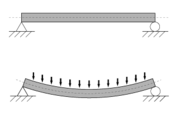
A statically determinate simply supported beam, bending under an evenly distributed load.

Any structure is essentially made up of only a small number of different types of elements:

  • Columns
  • Beams
  • Plates
  • Arches
  • Shells
  • Catenaries

Many of these elements can be classified according to form (straight, plane / curve) and dimensionality (one-dimensional / two-dimensional):

Contents

  • 1 Structural engineer
  • 2 History of structural engineering
  • 3 Structural failure
  • 4 Specializations
    • 4.1 Building structures
    • 4.2 Earthquake engineering structures
    • 4.3 Civil engineering structures
    • 4.4 Mechanical structures
  • 5 Structural elements
    • 5.1 Columns
    • 5.2 Beams
    • 5.3 Struts and ties
    • 5.4 Plates
    • 5.5 Shells
    • 5.6 Arches
    • 5.7 Catenaries
  • 6 Structural engineering theory
  • 7 Materials
  • 8 See also
  • 9 References
  • 10 External links
One-dimensional Two-dimensional
straight curve plane curve
(predominantly) bending beam continuous arch plate, concrete slab lamina, dome
(predominant) tensile stress rope Catenary shell
(predominant) compression pier, column Load-bearing wall

Columns

Main article: Column

Columns are elements that carry only axial force – either tension or compression – or both axial force and bending (which is technically called a beam-column but practically, just a column). The design of a column must check the axial capacity of the element, and the buckling capacity.

The buckling capacity is the capacity of the element to withstand the propensity to buckle. Its capacity depends upon its geometry, material, and the effective length of the column, which depends upon the restraint conditions at the top and bottom of the column. The effective length is K * l where l is the real length of the column.

The capacity of a column to carry axial load depends on the degree of bending it is subjected to, and vice versa. This is represented on an interaction chart and is a complex non-linear relationship.

Beams

Main article: Beam

A beam may be defined as an element in which one dimemsion is much greater than the other two and the applied loads are usually normal to the main axis of the element. Beams and columns are called line elements and are often represented by simple lines in structural modeling.

  • cantilevered (supported at one end only with a fixed connection)
  • simply supported (supported vertically at each end; horizontally on only one to withstand friction, and able to rotate at the supports)
  • continuous (supported by three or more supports)
  • a combination of the above (ex. supported at one end and in the middle)

Beams are elements which carry pure bending only. Bending causes one section of a beam (divided along its length) to go into compression and the other section into tension. The compression section must be designed to resist buckling and crushing, while the tension section must be able to adequately resist the tension.

Struts and ties

Main article: Truss

Little Belt: a truss bridge in Denmark

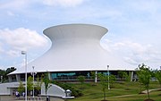
The McDonnell Planetarium by Gyo Obata in St Louis, Missouri, USA, a concrete shell structure

A masonry arch

1. Keystone 2. Voussoir 3. Extrados 4. Impost 5. Intrados 6. Rise 7. Clear span 8. Abutment

A truss is a structure comprising two types of structural element, ie struts and ties. A strut is a relatively lightweight column and a tie is a slender element designed to withstand tension forces. In a pin-jointed truss (where all joints are essentially hinges), the individual elements of a truss theoretically carry only axial load. From experiments it can be shown that even trusses with rigid joints will behave as though the joints are pinned.

Trusses are usually utilised to span large distances, where it would be uneconomical and unattractive to use solid beams.

Plates

Plates carry bending in two directions. A concrete flat slab is an example of a plate. Plates are understood by using continuum mechanics, but due to the complexity involved they are most often designed using a codified empirical approach, or computer analysis.

They can also be designed with yield line theory, where an assumed collapse mechanism is analysed to give an upper bound on the collapse load (see Plasticity). This is rarely used in practice.

Shells

Main article: Thin-shell structure
See also: Gridshell

Shells derive their strength from their form, and carry forces in compression in two directions. A dome is an example of a shell. They can be designed by making a hanging-chain model, which will act as a catenary in pure tension, and inverting the form to achieve pure compression.

Arches

Main article: Arch

Arches carry forces in compression in one direction only, which is why it is appropriate to build arches out of masonry. They are designed by ensuring that the line of thrust of the force remains within the depth of the arch.

Catenaries

Main article: Tensile structure

Catenaries derive their strength from their form, and carry transverse forces in pure tension by deflecting (just as a tightrope will sag when someone walks on it). They are almost always cable or fabric structures. A fabric structure acts as a catenary in two directions.

Structural Elements 101|Del Rio

Structural engineering – Wikipedia, the free encyclopedia

Burj Dubai, the world’s tallest building, currently under construction in Dubai

Structural engineering is a field of engineering dealing with the analysis and design of structures that support or resist loads economically. Structural engineering is usually considered a specialty within civil engineering, but it can also be studied in its own right.[1]

Structural engineers are most commonly involved in the design of buildings and large nonbuilding structures[2] but they can also be involved in the design of machinery, medical equipment, vehicles or any item where structural integrity affects the item’s function or safety. Structural engineers must ensure their designs satisfy given design criteria, predicated on safety (e.g. structures must not collapse without due warning) or serviceability and performance (e.g. building sway must not cause discomfort to the occupants).

Structural engineering theory is based upon physical laws and empirical knowledge of the structural performance of different geometries and materials. Structural engineering design utilises a relatively small number of basic structural elements to build up structural systems that can be very complex. Structural engineers are responsible for making creative and efficient use of funds, structural elements and materials to achieve these goals.[2]

Structural elements

A statically determinate simply supported beam, bending under an evenly distributed load.

Any structure is essentially made up of only a small number of different types of elements:

  • Columns
  • Beams
  • Plates
  • Arches
  • Shells
  • Catenaries

Many of these elements can be classified according to form (straight, plane / curve) and dimensionality (one-dimensional / two-dimensional):

Contents

  • 1 Structural engineer
  • 2 History of structural engineering
  • 3 Structural failure
  • 4 Specializations
    • 4.1 Building structures
    • 4.2 Earthquake engineering structures
    • 4.3 Civil engineering structures
    • 4.4 Mechanical structures
  • 5 Structural elements
    • 5.1 Columns
    • 5.2 Beams
    • 5.3 Struts and ties
    • 5.4 Plates
    • 5.5 Shells
    • 5.6 Arches
    • 5.7 Catenaries
  • 6 Structural engineering theory
  • 7 Materials
  • 8 See also
  • 9 References
  • 10 External links
One-dimensional Two-dimensional
straight curve plane curve
(predominantly) bending beam continuous arch plate, concrete slab lamina, dome
(predominant) tensile stress rope Catenary shell
(predominant) compression pier, column Load-bearing wall

Columns

Main article: Column

Columns are elements that carry only axial force – either tension or compression – or both axial force and bending (which is technically called a beam-column but practically, just a column). The design of a column must check the axial capacity of the element, and the buckling capacity.

The buckling capacity is the capacity of the element to withstand the propensity to buckle. Its capacity depends upon its geometry, material, and the effective length of the column, which depends upon the restraint conditions at the top and bottom of the column. The effective length is K * l where l is the real length of the column.

The capacity of a column to carry axial load depends on the degree of bending it is subjected to, and vice versa. This is represented on an interaction chart and is a complex non-linear relationship.

Beams

Main article: Beam

A beam may be defined as an element in which one dimemsion is much greater than the other two and the applied loads are usually normal to the main axis of the element. Beams and columns are called line elements and are often represented by simple lines in structural modeling.

  • cantilevered (supported at one end only with a fixed connection)
  • simply supported (supported vertically at each end; horizontally on only one to withstand friction, and able to rotate at the supports)
  • continuous (supported by three or more supports)
  • a combination of the above (ex. supported at one end and in the middle)

Beams are elements which carry pure bending only. Bending causes one section of a beam (divided along its length) to go into compression and the other section into tension. The compression section must be designed to resist buckling and crushing, while the tension section must be able to adequately resist the tension.

Struts and ties

Main article: Truss

Little Belt: a truss bridge in Denmark

The McDonnell Planetarium by Gyo Obata in St Louis, Missouri, USA, a concrete shell structure

A masonry arch

1. Keystone 2. Voussoir 3. Extrados 4. Impost 5. Intrados 6. Rise 7. Clear span 8. Abutment

A truss is a structure comprising two types of structural element, ie struts and ties. A strut is a relatively lightweight column and a tie is a slender element designed to withstand tension forces. In a pin-jointed truss (where all joints are essentially hinges), the individual elements of a truss theoretically carry only axial load. From experiments it can be shown that even trusses with rigid joints will behave as though the joints are pinned.

Trusses are usually utilised to span large distances, where it would be uneconomical and unattractive to use solid beams.

Plates

Plates carry bending in two directions. A concrete flat slab is an example of a plate. Plates are understood by using continuum mechanics, but due to the complexity involved they are most often designed using a codified empirical approach, or computer analysis.

They can also be designed with yield line theory, where an assumed collapse mechanism is analysed to give an upper bound on the collapse load (see Plasticity). This is rarely used in practice.

Shells

Main article: Thin-shell structure
See also: Gridshell

Shells derive their strength from their form, and carry forces in compression in two directions. A dome is an example of a shell. They can be designed by making a hanging-chain model, which will act as a catenary in pure tension, and inverting the form to achieve pure compression.

Arches

Main article: Arch

Arches carry forces in compression in one direction only, which is why it is appropriate to build arches out of masonry. They are designed by ensuring that the line of thrust of the force remains within the depth of the arch.

Catenaries

Main article: Tensile structure

Catenaries derive their strength from their form, and carry transverse forces in pure tension by deflecting (just as a tightrope will sag when someone walks on it). They are almost always cable or fabric structures. A fabric structure acts as a catenary in two directions.

Mechanical Structures 101 | Victoria

Mechanical structures

An Airbus A380, the world’s largest passenger airliner.

The design of static structures assumes they always have the same geometry (in fact, so-called static structures can move significantly, and structural engineering design must take this into account where necessary), but the design of moveable or moving structures must account for fatigue, variation in the method in which load is resisted and significant deflections of structures.

The forces which parts of a machine are subjected to can vary significantly, and can do so at a great rate. The forces which a boat or aircraft are subjected to vary enormously and will do so thousands of times over the structure’s lifetime. The structural design must ensure that such structures are able to endure such loading for their entire design life without failing.

These works can require mechanical structural engineering:

  • Airframes and fuselages
  • Boilers and pressure vessels
  • Coachworks and carriages
  • Cranes
  • Elevators
  • Escalators
  • Marine vessels and hulls


Structural Engneering 101 | Victoria, Texas

Structural engineering – Wikipedia, the free encyclopedia

Burj Dubai, the world’s tallest building, currently under construction in Dubai

Structural engineering is a field of engineering dealing with the analysis and design of structures that support or resist loads economically. Structural engineering is usually considered a specialty within civil engineering, but it can also be studied in its own right.

Structural engineers are most commonly involved in the design of buildings and large nonbuilding structures but they can also be involved in the design of machinery, medical equipment, vehicles or any item where structural integrity affects the item’s function or safety. Structural engineers must ensure their designs satisfy given design criteria, predicated on safety (e.g. structures must not collapse without due warning) or serviceability and performance (e.g. building sway must not cause discomfort to the occupants).

Structural engineering theory is based upon physical laws and empirical knowledge of the structural performance of different geometries and materials. Structural engineering design utilises a relatively small number of basic structural elements to build up structural systems that can be very complex. Structural engineers are responsible for making creative and efficient use of funds, structural elements and materials to achieve these goals.

Earthquake Engineering 101 | San Antonio

Structural engineering – Wikipedia, the free encyclopedia

Burj Dubai, the world’s tallest building, currently under construction in Dubai

Structural engineering is a field of engineering dealing with the analysis and design of structures that support or resist loads economically. Structural engineering is usually considered a specialty within civil engineering, but it can also be studied in its own right.[1]

Structural engineers are most commonly involved in the design of buildings and large nonbuilding structures[2] but they can also be involved in the design of machinery, medical equipment, vehicles or any item where structural integrity affects the item’s function or safety. Structural engineers must ensure their designs satisfy given design criteria, predicated on safety (e.g. structures must not collapse without due warning) or serviceability and performance (e.g. building sway must not cause discomfort to the occupants).

Structural engineering theory is based upon physical laws and empirical knowledge of the structural performance of different geometries and materials. Structural engineering design utilises a relatively small number of basic structural elements to build up structural systems that can be very complex. Structural engineers are responsible for making creative and efficient use of funds, structural elements and materials to achieve these goals.[2]

Earthquake engineering structures

Earthquake engineering structures are those engineered to withstand various types of hazardous earthquake exposures at the sites of their particular location.

Earthquake-proof and massive pyramid El Castillo, Chichen Itza

Earthquake engineering is treating its subject structures like defensive fortifications in military engineering but for the warfare on earthquakes. Both earthquake and military general design principles are similar: be ready to slow down or mitigate the advance of a possible attacker.

The main objectives of earthquake engineering are:

Snapshot from shake-table video [1] of testing base-isolated (right) and regular (left) building model

  • Understand interaction of structures with the shaky ground.
  • Foresee the consequences of possible earthquakes.
  • Design, construct and maintain structures to perform at earthquake exposure up to the expectations and in compliance with building codes.

Earthquake engineering or earthquake-proof structure does not, necessarily, means extremely strong and expensive one like El Castillo pyramid at Chichen Itza shown above.

Now, the most powerful and budgetary tool of the earthquake engineering is base isolation which pertains to the passive structural vibration control technologies.

Contents